
|
|
|
|
Here you will find more specific discussions about each relevant aspect of a coil gun. The solenoids Everybody may have already seen a pinball game, correct? So, if you ever wonder what is responsible for moving the flippers to hit the ball, then you will find the device that uses electricity to generate a linear movement, which by its turn will move the flippers. The solenoid is made of several windings of special wire (usually copper); when current passes through the wire, each winding generates a small magnetic field, which is added to the field generated by the other windings, thus generating a bigger magnetic field. So, we can assume that the more turns we can wind the coil, bigger will be the field (but also bigger will be the electrical resistance). After some time searching the internet, I noted that almost all the coil gun projects and sites found talks about using many coils (3 ~ 30) and use some scheme to synchronize the coils activation. Actually I am trying to find a way to use just one longer coil, instead of many coils. There will be some tricky problems, such as the time needed to activate ("load with energy") and deactivate the coil; the bigger burst of energy needed, in contrast with the smaller energy needed to activate separate smaller coils; and the balance of wire thickness, number of turns, current/voltage that will be utilized. Other problem is the half length usable part of common coils. That's why I reached, so far, the coil model that can be seen in the photos page. The results of the first experiments with it were good to me, and indicated that is possible to build a coil which have the position, where the projectile still get accelerated, near one of the extremes of the coil (in my case, the thicker part of the coil). I just call it a "trumpet coil", because it looks like that instrument. The projectiles As the objective of a coil gun is to launch a projectile (hopefully at high speeds), some time must be reserved to this subject. To be continued . . . The timing circuit The timing will be given by software, using C++ at DOS environment, until the experiments reveal themselves more conclusive. So, actually I use a PC with an I/O board, connected to the rest of the circuits by means of some HP high speed optocouplers. Recently I gathered some info and specs about opto devices able to handle high speed events, from 1 MHz and beyond. I intend to use a PC to control the first prototypes, and I expect to be able to do a good I/O pooling in the order of about 350 kHz. My first program was able to register events in the order of 2 to 3 microseconds. Since open loop systems are harder to calibrate, I will use high speed infra red pairs of LED's and photodiodes in order to read the projectile position. In the first stage of the experiments, the power drives will be handled by some TIP 142 transistors connected in parallel so a bigger capacity of current can be achieved, although that's not a common configuration (at least to me). The "trumpet coil" will have an important rule on this matter, because would be useless to read the projectile position at the end of some coil, because the projectile would have already passed by the middle point of the coil, which is the end of the usable part of the coil. Inductance Actually I'm studying the problems that arise from coil inductance, mainly the activation/deactivation times associated with high current-turns coils (made with many turns). One "solution" to it would be the use of tremendous current and few turns. Just to make you guys curious, I'll put here the conclusions I found, before the calculations: the ideal coil would be as long as possible, with an inner barrel as tight as possible; the more resistance that would be possible (and acceptable) and the biggest voltage that we could achieve; also, the thicker wire as possible (because we also want the most amp-current possible). This leads me to use just one long special coil. The bigger resistance would be interesting because of its influence on the formula, but with smaller resistance, we can achieve higher currents. Well, it will take a little longer to achieve the steady current because of the inductance effect, but also, before it reaches steady state, we also will have a bigger current flowing in the coil (even before reaching steady state), what gives us more magnetic field. These are the calculations that were made in order to achieve these conclusions: Considering the inductance and current formulas bellow, with the respective variables L = inductance (H) S = spire area(cm^2) n = number of turns C = length of the coil (meters) i = current (A) i0 = initial current (A) - steady state current after the solenoid has been energized R = electrical resistance (ohms) t = time (seconds) r2 = Radius of the outside of the coil (meters) r1 = Radius of the inside of the coil (meters) The Inductance formula (1) L = [( 31.6 * n2 * r12 ) / (6 * r1 + 9 * C + 10 * (r2 - r1))] / 1000000 (Obs: this one I used was found on the net "Wheeler Formulas for Inductance©", and are primarily based on empirical measurements. The original result is in microhenry, so I just putted a "/1000000") The formula is valid for a multi layer air core solenoid. The Current by Time (2) and (3): Growth: Decreasing:
There is a little Excel sheet which allows some experimentation with these formulas; the values on it are from the first coils built (see the photos page).
Imagine you have the coil with 0.6 ohms (the first graphic) and now
replace the value by 6 ohms; take the 12V and replace it with 120V; now watch the
shape of the curve.
Considering now the characteristics of the trumpet - shape coil: about 7.2 cm length. Now, my primary objective: a projectile launched at a speed of 100 m/s. This speed also means a speed of 10cm / millisecond. Well, my conclusion is how can I do the control? if I could handle the timing needed, the power delivered would also be much below the optimal values; and even worst, at a moment when the projectile needs the most power possible. If the coil is a regular cylinder shape coil, the usable length would be of about 3.6 cm. The conclusions about this case study: we have a device with a possible timing control of 2 milliseconds, planning to use it with a situation where in 1.0 millisecond, the projectile travels about 1,5 full coil length distance! If you wish, download the xls file and play a little with resistance, length, diameter and number of turns (4 variables) just to verify how to handle the timing issue (change the deltaT also to view the effect on the curve), never forgetting that as we change the values, also the current and amp-current (directly related with the magnetic strength) changes. Is not easy to find a set of values, mainly when the desired speeds become greater -> my case :-(. An alternative for the inductance would be to wind a coil with few turns and use a capacitor bank to give it a pulse of some KA (Kilo Amps). Well, now the problems turns back to the circuitry used. That's one of the reasons why I'm studying the possibility to make the Electro mechanical approach to work. That's a point that activated my interest in using small force high speed activation coils in a circular path (see Other Ideas page) before launching the projectile. Hits since 03/08/1999: This page was last updated on 05/15/00. © 1999 by Lissandro |
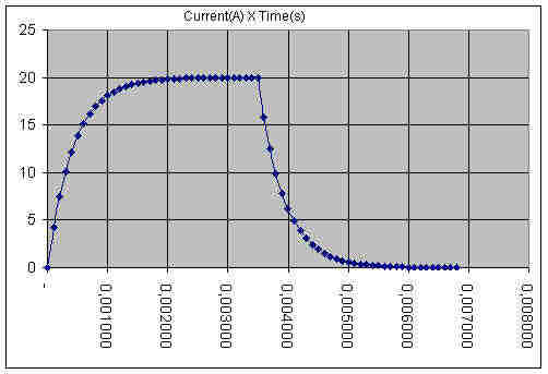 This graphic shows the theoretical current in my coils
(provided a good driver) based on the equations and the characteristics of the coils. As
can be seen here and in the sheet
This graphic shows the theoretical current in my coils
(provided a good driver) based on the equations and the characteristics of the coils. As
can be seen here and in the sheet 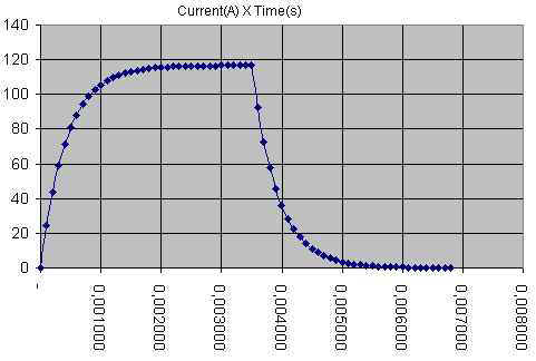 In this graphic, on the other hand, the voltage applied is
70V. As was said in the begginning of this matter, having the bigger resistance
possible is not exactly like that, what was meant is that the shape of the control curve
becames better. Playing with resistance in the excell sheet the effect on the signal
raising speed becames explicit. But, as the fellow Otto brought to me, in terms of brute
power, it is really more interesting having less resistance, because the time of current
rising becomes smaller, thus contributting to our special timming needs. See, in the first
case, we obtain 4.19 A in 100 µs (and 18A in 1000 µs). In the second case, using 70V
instead of 12V, we obtain 24.45A in 100 µs (and 105A in 1000 µs). In the practice, we
obtain more power in the same time that before.
In this graphic, on the other hand, the voltage applied is
70V. As was said in the begginning of this matter, having the bigger resistance
possible is not exactly like that, what was meant is that the shape of the control curve
becames better. Playing with resistance in the excell sheet the effect on the signal
raising speed becames explicit. But, as the fellow Otto brought to me, in terms of brute
power, it is really more interesting having less resistance, because the time of current
rising becomes smaller, thus contributting to our special timming needs. See, in the first
case, we obtain 4.19 A in 100 µs (and 18A in 1000 µs). In the second case, using 70V
instead of 12V, we obtain 24.45A in 100 µs (and 105A in 1000 µs). In the practice, we
obtain more power in the same time that before.